NTSC Atari 800 shows good video on "modern" PAL monitors using a UAV video upgrade board
Introduction
The Atari 800 is an iconic model from the very early days of consumer microcomputers. Being such, I'd always wanted one. I managed to score its cut-down sibling, the Atari 400, in 2008 but the 800 model had proved elusive. PAL versions were particularly unobtainable, yet these were the variants needed for New Zealand televisions.
A couple of weeks ago, an undamaged and working NTSC version appeared on our Trade Me auction site. It wasn't PAL, but the seller would also throw in a UAV video upgrade board. Some research revealed this is a modern piece of hardware designed to improve the video from classic Atari computers. The seller had recently installed one in his NTSC Atari 400 with good results on his PAL display.
In my experience, video adaptors for retro-computers have a "results may vary" history so I wasn't holding my breath. However, whether it worked or not didn't matter as I wanted an 800 to complete my collection. If I could get it looking good in PAL, that would be a bonus.
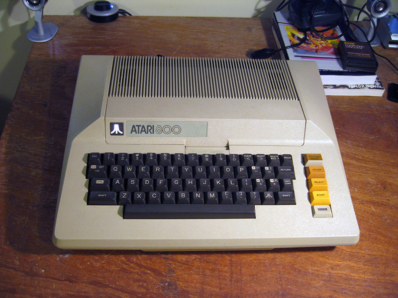
Figure 1. My new Atari 800. Beautiful!
Once the machine arrived, I tested it with composite video on one of my televisions. Surprisingly, despite the computer being NTSC and the television being PAL I could see a colour image. On closer inspection though, the colours were dull and the margin of the sprites ill-defined. This was to be expected. Time to install the UAV and see what happens!
The UAV
The UAV is a small card, containing a number of surface-mount components (Figure 2). The maker of the board, Bryan of the AtariAge forums, had written a very clear procedure for installation in a forum post (see 1/2 way down the page) . I followed this recipe closely.
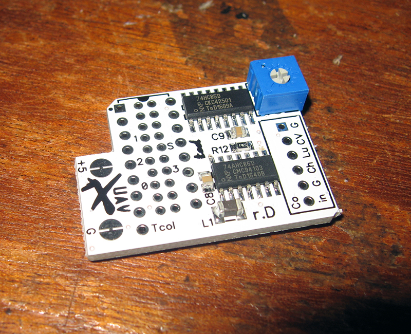
Figure 2. The UAV video board
Essentially the UAV needed to be mounted over the 4050 chip, provided with power and ground, and leads wired to video outputs in the Atari.
Installation
Armed with my trusty Atari 400-800 Service Manual (or at least the PDF) I started removing screws. Disassembling an Atari 800 is not straightforward. The computer is built like a tank, comprising of several boards with a lot of molded aluminium shielding! However, in the fullness of time I had the main board exposed (Figure 3).
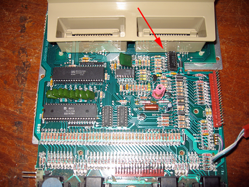
Figure 3. Atari 800 main CPU circuit board (The red arrow shows the 4050 chip)
The first task was to remove the 4050 chip, so I could attach some pins to its legs.
Wiring up the 4050 chip to the UAV
First I snipped off excess wire from some resistor legs I had lying around. The task was to solder these to the legs of the 4050, then in turn to the UAV. Wires were needed to pins 5,7,9,11,14 and also a power wire to pin 1 to supply 5V to the board.
Using a trusty pair of clamps the wires were soon attached (Figures 4 and 5).
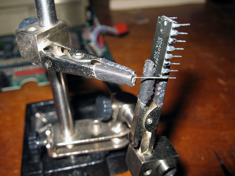
Figure 4. Attaching a lead to the 4050 IC
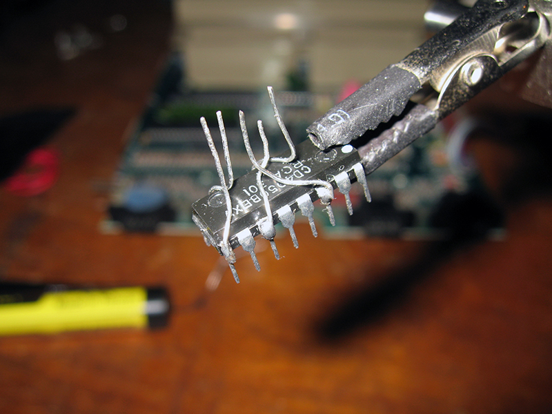
Figure 5. All wired (except the 5V power wire) attached and ready for the UAV
The pins are bent in that configuration so they would match labeled holes in the UAV board. This is what they needed to match up to:
pin 5 to 0
pin 9 to 1
pin 14 to 2
pin 11 to 3
pin 7 to S
pin 1 to 5V pad on top
I added the 5V wire on pin 1 then pushed the other pins through the appropriate holes and soldered them in. The 5V wire was then soldered to a pad at the top of the UAV. Figure 6 shows the result.
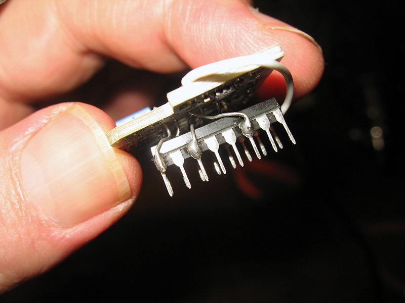
Figure 6. UAV board wired into the 4050
I checked very carefully to ensure there was clear air between those crossing bare leads. I'm sure if they were touching one another nothing good would come of it. (-:
The next task was to solder on the four colour signal output leads to the UAV (CV, Luma, Chroma and Colour In), then mount the chip (together with its piggybacked board) back into the socket from which it came (Figure 7).
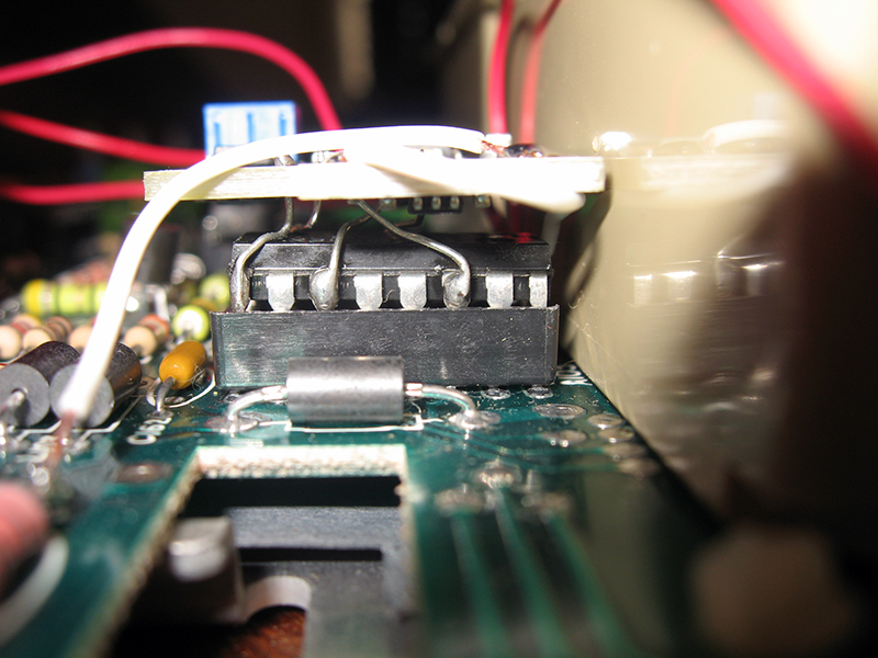
Figure 7. 4050 IC and UAV mounted in the socket. The ground wire has also been attached from the pad at the top of the UAV to the left leg of C193
I used a small flat bladed screwdriver with a long neck to push down on the top of the chip at various points along its length to ensure it was well secured in the socket.
Next, as per Bryan's instructions, I pulled the right legs of R189, L104 and L105 clear of their pads (melting the solder with a soldering iron of course), and attached the UAV's video wires to them thus:
CV to the now empty pad of L104
Luma to the now empty pad of R189
Chroma to the now empty pad of L105
Finally I attached the UAV's "Color In" wire to the right side of R196, a resistor hiding around the right side of the cartridge bays (Figure 8).
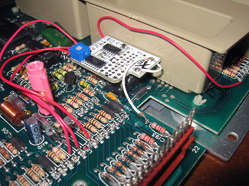
Figure 8. UAV colour output leads all wired up
The modification was complete (Figure 9).
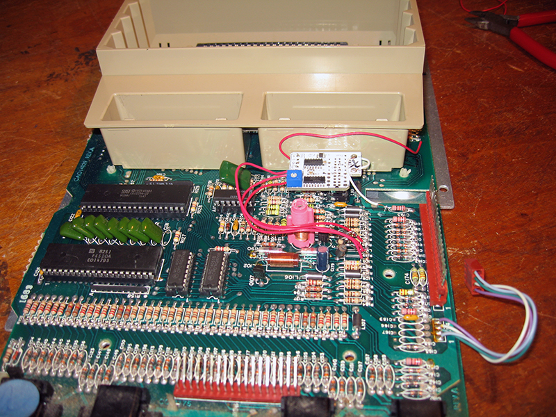
Figure 9. Wiring complete!
Now all I needed to do was reassemble and hoped that it worked!
Testing
Soon everything was back together, the computer was hooked up to a PSU and monitor and ready to be fired up. With my heart in my mouth I flipped the switch. Instantly a picture appeared and it was immediately apparent that the procedure had worked! Hooray! Colours were brighter, well focused and there was no bleeding around the edges.
Here are some comparative photos using the ROM-based memo pad (Figures 10 and 11):

Figure 10. Memo Pad on NTSC Atari WITHOUT the UAV fitted
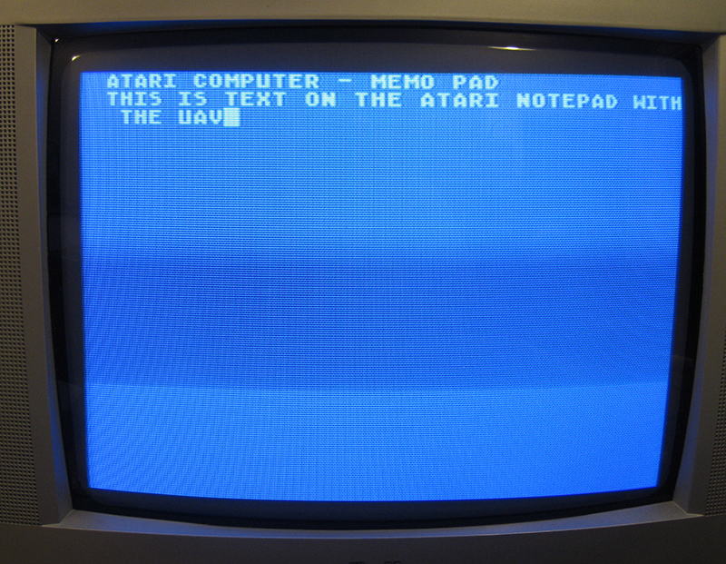
Figure 11. Memo Pad on NTSC Atari WITH the UAV fitted
Notice the brighter characters. This looks similar (and actually better) to the screen experience with my Atari 400 and 800XL. Ignore the wavy lines...those are an artifact of the camera.
Now how about a colourful arcade game (Figures 12 and 13):

Figure 12. Galaxians on NTSC Atari WITHOUT the UAV
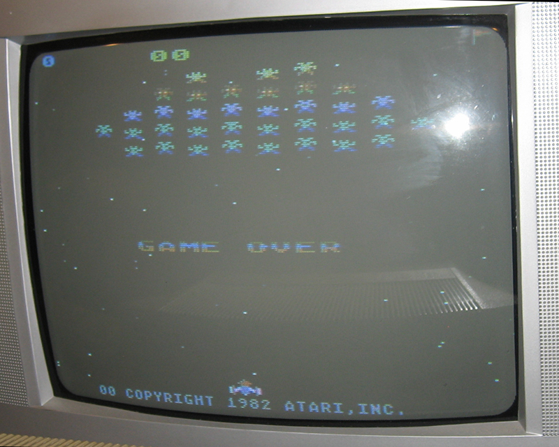
Figure 13. Galaxians on NTSC Atari WITH the UAV
Things look better here as well, even though the flash from the camera dulls things a little. Note the better defined ship and letters at the bottom.
I tested the 800 on another television I had. Same result. Beautiful colour! It seems adding the UAV video adaptor, although fiddly, was completely the right call. My NTSC Atari 800 now appears PAL-capable, at least on the two televisions/monitors I have.
CAUTION: Results may still vary
Before Atari NTSC owners in PAL-land reading this rush out and buy the UVA, it's worth noting that technically, this shouldn't have worked. The UAV is not a NTSC<-->PAL converter...it simply cleans up the Atari video. Even the inventor of the card, Bryan, was surprised with this result. I suspect it worked because the TV/monitors I used were not that ancient, being made around early 2000 or so. It's known that many (relatively) modern PAL CRT TV/monitors can handle NTSC through composite video input, at least to a degree. Other monitors, especially early ones may not be able to.
I have not tested the RF output. I've very sure this NTSC Atari would NOT be able to tune into a PAL channel via RF and show colour.
Reflections
I'm very pleased to have a working Atari 800 at last. I'm even more pleased that it looks good with PAL. Disassembly and wiring up took a few (careful) hours but it was worth it. I half expected to see black and white video or no video when I flicked the switch. Relief was as much an emotion as satisfaction.
Bryan at Atariage has produced a highly useful product for this line of retro-computers. If you are looking at fitting one yourself to an Atari, best to check out the support thread on the forums here. As mentioned above, specific instructions on the Atari 800 mod are about 1/2 down on this page. Although I've outlined the main steps in the context of what I did, best use those original instructions for your own work.
Many thanks to Antony, the seller of this Atari 800, for the complementary UAV. Until he told me, I did not know such a thing existed. The good thing about the adaptor is that it's completely reversible, so that originality can be restored if needed.
In the meantime, time to shoot some alien invaders!
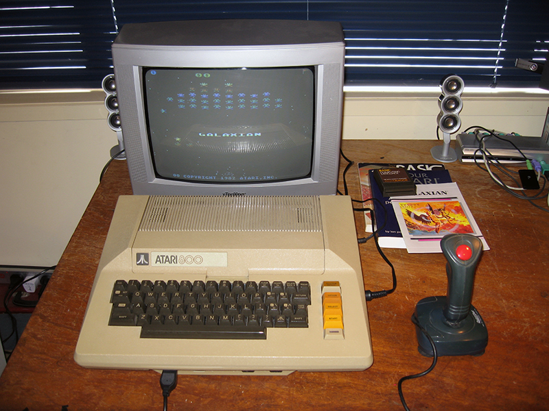
Figure 14. Time to relax with a good game of chess..opps..hang on, this is an Atari...I mean Galaxians!
Tez
6th March, 2018